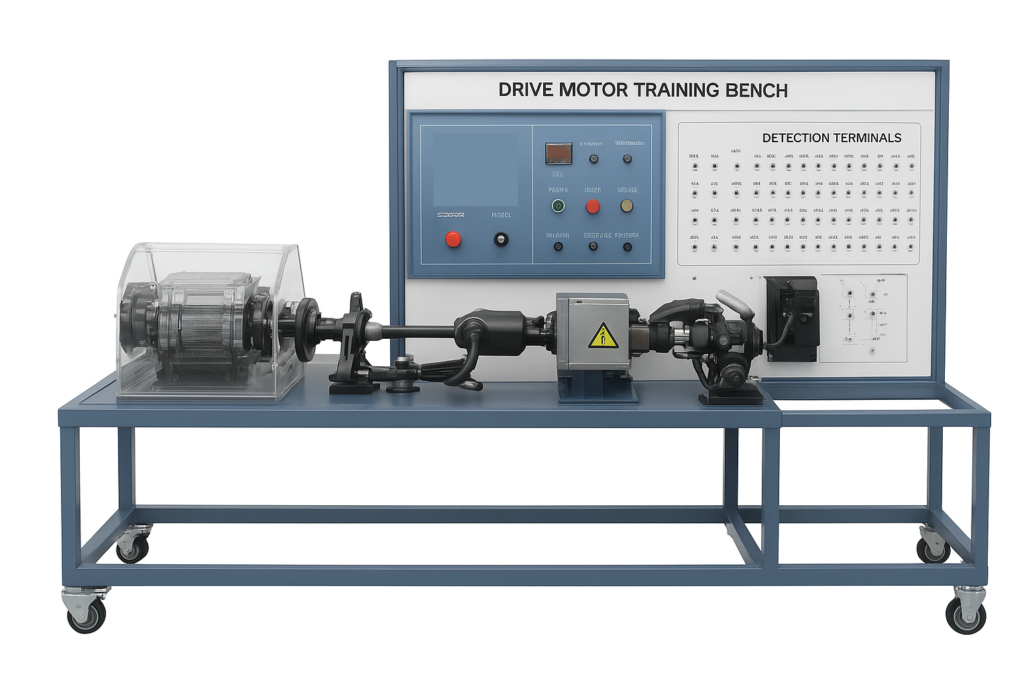
PST-DRMTKM-2014 DRIVE MOTOR TRAINING BENCH
GENERAL SPECIFICATION / DESCRIPTION
- Drive Motor Training Bench must be a fully operational simulator of an electric vehicle’s drive system, encompassing all critical subsystems, for training purposes. It must be equipped with a fault simulation system to provide practical, hands-on training in diagnosing and analyzing a wide range of system and component failures.
- It must feature a comprehensive set of accessible detection terminals, allowing a trainee to measure and analyze signals from various components, including resolver and wheel speed sensors, the cooling pump, charging systems, and the high-voltage power distribution network.
- The bench must include a permanent magnet synchronous drive motor assembly, a power domain controller, a transmission shaft, a steering knuckle assembly, an electronic parking system, a cooling system, a brake pedal, an accelerator pedal, a gear mechanism, a combination instrument, etc.
- The drive motor acceleration, deceleration, braking, parking and other functions can be controlled by operating the control panel.
- Each component is fixed to the platform according to the relative position of the original vehicle, intuitively displaying the structural principle of the pure electric vehicle drive motor control system, and meeting the structural cognition and detection functions of the system.
TECHNICAL SPECIFICATION
The set comprises:
- voltage power voltage (Vdc): 403 approx.
- voltage control working power supply (Vdc): 12 approx.
- Power domain controller peak power (kW): 150 approx.
- Power domain controller peak current (A): 450 approx.
- Power domain controller cooling method: water cooling.
- Motor controller protection level: IP67 approx.
- Maximum torque of drive motor (Nm): 310N approx.
- Drive motor peak power (kW): 150 approx.
- Charging input: 220V/32A/50Hz approx.
- DC/DC output: 13.8V / 126A approx.
- Dimensions (mm): 1900 (L) × 950 (W) × 900 (H) approx.
- Working environment temperature (℃): -20℃ ~ +50 approx.
- System shall provide the capability for the detection and fault analysis of resolver sensors.
- System must provide components and test points for the inspection and fault analysis of the drive motor cooling water pump.
- Platform shall facilitate the detection and fault analysis of the wheel speed sensors.
- System must support the detection and fault analysis of the DC charging system.
- Equipment must enable the detection and fault analysis of the drive motor temperature circuit.
- Platform should be designed for the inspection and fault analysis of the brake switch and accelerator pedal.
- System is required to allow for the detection and fault analysis of shift mechanism control signals.
- The system shall support the detection and fault analysis of the high-voltage power distribution systems.
- The capability for detection and analysis of the high and low voltage interlocking system circuit is a required feature.
- Platform must be designed to allow for the testing and analysis of high-voltage fuses.
- The system will provide for the detection and principal analysis of the DC-DC converter.
- System’s configuration needs to support the detection and principal analysis of the AC charging system.
- Diagnostic System Interface: Supports the use of a special decoder for new energy vehicles to perform diagnostic functions, including reading and clearing fault codes, viewing dynamic data streams, and setting parameters.
- Measurement and Analysis Capability: The platform is equipped with detection terminals allowing for circuit signal analysis using multimeters and oscilloscopes.
- Fault Simulation System: Includes a wireless fault setting system capable of simulating line disconnection faults in the power domain controller.
- Component Visibility: The motor controller features a transparent acrylic upper cover for clear observation of its internal structure, including filter capacitors, sensors, and control circuits.
- The accelerator pedal is designed with an integrated speed limit to ensure the stability of equipment operation.
- The operation panel must be designed to meet ergonomic
ACCESSORIES
- One (1) unit original permanent magnet synchronous drive motor
- One (1) unit high-voltage eight-in-one controller.
- Two (2) unit drive shafts.
- Two (2) unit steering knuckle assemblies.
- One (1) unit brake master cylinder.
- Two (2) unit brake slave cylinders.
- One (1) unit electronic parking system.
- One (1) unit cooling system.
- One (1) unit brake pedal.
- One (1) unit accelerator pedal.
- One (1) unit gear shifting mechanism.
- One (1) unit combination instrument.
- One (1) unit one-button start switch.
- One (1) unit wireless fault setting system (10 circuit breaker faults).
- A measuring panel must include approx. 43 detection terminals.
DOCUMENTATION
- Original Manufacturer Product Catalogue in Malay or English – 4 sets (include one original).
- Operation and maintenance manual in Malay or English – 4 sets (include one original).
Work calibration certificate.

