HV Trainer Electric Drives and HV Systems in Vehicles
- Product Information
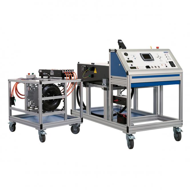
- Functional model of e-drives and HV systems in motor vehicles
The functional model E-drives and HV systems in motor vehicles consists of a drive module and a power supply and control module. The HV system operates with an operating voltage of 96 volts.
- A complete power supply unit with electronic battery management (BMS), an integrated charger for the HV battery, a control unit with motor management system, all necessary safety components,
- Mennekes charging connection (type 2) are built on. The HV system can be enabled either via a service disconnect in the 12 V circuit or via a service disconnect in the HV circuit (in the HV battery).
- In addition, the training system has a rescue disconnection point to represent the disconnection of an accident- damaged vehicle.
- The HV battery, with 96 volts nominal voltage, is equipped with 32 LiFePO4 / 40 Ah cells. The battery management system has a Bluetooth interface.
- The status (voltage, temperature, balancing rate during the charging process) of each individual battery cell can be displayed via an associated app (Android).
- Voltage disconnection with service disconnect high-voltage circuit
- Voltage disconnection with service disconnect low-voltage circuit
- Voltage disconnection with rescue disconnection point
- Determine absence of voltage
- Secure against reconnection
- Measuring the DC link capacitor charge and discharge curve
- Locate defective battery cells by measurement
- Replacing battery modules
- Check connector between cells for contact resistance
- Function test of contactors
- Checking the safety line (interlock circuit)
-
- Product Specification
- Measurement possibilities:
-
- Check motor encoder and motor temperature sensor
- Display load simulation (uphill drive) visibly and measurably
- Programming of the HV controller with hand-held programmer or PC interfacePhase voltage and phase signal (U, Checking the insulation monitor V, W) to the e-motor
-
- Measurement possibilities:
- 12 Von-board voltage
- HV battery voltage
- Potentialequalisation measurement
- Insulation resistance measurement
- Insulation monitor signal (PWM signal)
- Inverter intermediate circuit voltage
- CP signal at charging socket (communication with charging station)
- Safety line (interlock circuit and interlock signal voltage) Input DC/DC converter (plus and minus)
- Output DC/DC converter (plus and minus)
- Temperature and voltage of a single battery cell (via BMS)
- Current sensor signal
- E-motor speed and temperature sensor signal
2.29.2.2 The functional model has an integrated fault circuit with which 10 faults in the power supply module and 16 faults in the drive module can be switched. The fault circuit is controlled with a specially developed app (Android) via Bluetooth with a tablet or smartphone (included in the scope of delivery).
- Fault circuit in the drive
- DC link capacitor residual energy discharge does not work
intermediate circuit capacitor residual energy discharge too slow
- Product Specification
- coil main contactor in drive module interrupted
- main HV contactor in drive module defective
- main HV contactor in drive module stuck/welded together
- DC/DC converter does not switch on
- motor temperature sensor defective
- Motor encoder phase line interrupted
- CAN bus disturbed
- Motor phase 0/V) interrupted
- insulation fault HV+ warning
- Insulation fault HV+ alarm
- Insulation fault HV- warning
- Insulation fault HV- alarm
- Insulation problem HV+
- Insulation problem HV-
- Fault circuit in the battery module:
- insulation resistance below the warning threshold
- insulation resistance below the alarm threshold
- interlock service disconnects interrupted
- Fault circuit in the battery module:
- overtemperature of a battery cell
- interruption of the DC line of the charger
- HV+ battery contactor does not close
- HV+ battery contactor stuck/welded
together
- charging communication interrupted
- AUX module supply HV+ line
interrupted
- cell module communication interrupted
- Learning Objectives
- Observance of accident prevention regulations
- Avoiding hazards when handling electrical current and hazardous
- Learning Objectives
substances
Selection of suitable and safe testing and measuring equipment
- Handling and use of safety equipment
- Application of manufacturer-specific test routines
- Disconnecting high-voltage components, securing them against being switched on again, ensuring that they are voltage-free
- Planning the diagnosis and repair of the high-voltage system and its components An accessory box with the following contents is supplied with the HV Trainer:
- 1x Charging cable 16A 1- phase Schuko-Mennekes
- 1x Service disconnect plug
- 1x Lock for service disconnect
- 2x Key for lock Service- Disconnect
- 1x Toggle for battery main switch 12V
- 1x Interlock bridging cable
- 1x Tablet for fault circuit
- 4x Safety test leads (2x red and 2x black, 1x each in
108cm and 1x in 30cm)
- 1x “High-voltage switched on” sign – red
- 1x “High-voltage switched off’ sign – white
- 1x USB charging cable for tablet
- 2x Ignition key
- 1x Battery charger 6/12V 4A
- 2x Keys for side doors
- 1x CD software Curtis 1314 incl. connection cable
1x Warning pyramid
- Drive module:
- Dimensions: L x W x H: 100 x 90 x 115cm
- Weight: 110 kg
- Battery module:
- Dimensions: L x W x H: 170 x 90 x 140cm
- Weight: 230 kg
- Mains connection: 230 volt/ 16 ampere

