Basic Pneumatic Trainer
Product Descriptions:
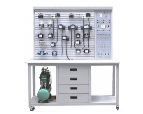
This device is designed and made based on “ Pneumatic transmission”, “Pneumatic control technology”. It can be used as the comprehensive test-bench of the mechanical, electrical and pneumatic transmission. Students can get more accurate understanding of the structure of pneumatic components, pneumatic control loop theory and design methods through operation.
Main technical parameters:
- Size: 1500mm*700mm*1720mm;
- Power: input AC220V, output DC24V/2A,
- Air compressor: 360W, AC220V,
- Capacity: 10L,
- Rated output pressure: 0.7MPa
Features:
- The training bench panel uses aluminum profile, the components can be installed onto the panel very conveniently.
- Experimental device consists of training tables and training units, pneumatic and electrical control devices and other components.
- Equipped with pneumatic components, and are equipped with transition plate for easy and optionally placing the components in the experimental panel, circuit lap using quick-change connectors to facilitate convenient and quick disconnect.
- Air pressure is low, electrical control uses low voltage 24V DC; training pneumatic control circuit is safe and reliable, with manual, automatic, sequential and other functions.
- Training control unit can also use independent relay control unit to control electrical.
Basic experiments:
- Single-acting cylinder commutation circuit
- Double-acting cylinder commutation circuit
- Single-acting cylinder speed control loop
- Double-acting cylinder-way flow control loop
- Double-acting cylinder bi-speed circuit
- The speed loop for access
- Buffer circuit
- The secondary pressure control loop
- High and low voltage conversion circuit
- Counting loop
- The delay loop
- Overload protection circuit
- Interlock circuit 1
- Dingle-cylinder reciprocating control loop
- Dingle-cylinder reciprocating continuous loop
- Linear cylinders, rotary cylinders loop sequence of actions
- Multi-cylinder sequence of actions loop
- Twin synchronized action loop
- Dour-cylinder linkage loop
- The unloading circuit
- Shuttle valve applications loop
- Quick exhaust valve application circuit
- Loaded latch circuit


